Autocycle — Control Design and Firmware
While at the University of Maryland, I was a part of and helped lead Team Autocycle, a student research team working to design and build a self-driving bicycle. In order to make the Autocycle work, it needed a robust control system to allow it to balance itself and follow commanded trajectories. The control design and implementation was the primary task I applied myself to, learning linear system theory in the process, and developing my skills in writing complex robotic firmware in C++.
Uncontrolled Simulation
At the beginning of the project, no one on the team (including myself), knew much about linear system theory, but we understood that dynamic systems governed by sets of linear differential equations (such as those we had found in the existing literature) could be simulated. As such, I set out to build such a simulator so we could better understand how a bicycle would behave under various control regimes.
The simulator was written Python using the NumPy an SciPy libraries for mass numerical computation and differential equation solvers. The results were then plotted using MatPlotLib in TKinter interface.
Kalman Filtering
After having built the simulator and tested out a few simple control strategies for feasibility, we assembled the first instrumented prototype of the self-driving bike, complete with a drive motor, a servo motor for steering, and gyroscopes and accelerometers for sensing. However, it very quickly became apparent that the raw sensor readings were wholly inadequate for measuring our current orientation, with far too much noise introduced to the accelerometers.
As such, I implemented a Kalman filter in C++ on top of a linear algebra library to fuse the various sensor readings into optimal estimates of state.
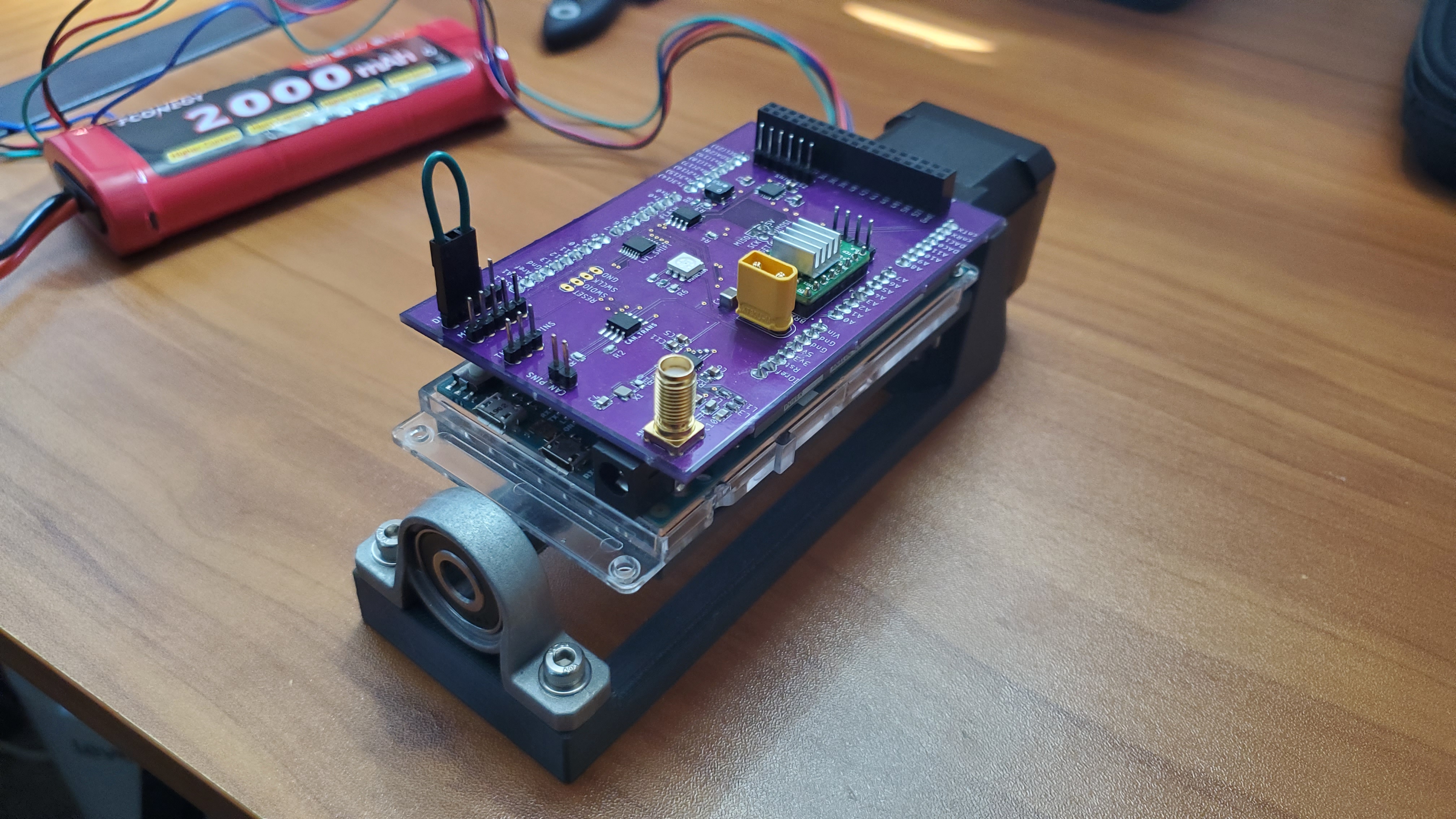
While the sensor variances were found empirically, the appropriate process covariances were found by tuning using the rig shown below, which moved the microcontroller (with sensor package) through a known set of orientations (by means of stepper motor).
Full State Feedback Control
While our first simulations and control attempts used a naive PID system, I quickly realized that this was not the right tool for the multi-input, multi-output system we had. I proceeded to read up on linear system theory and devise a full state feedback controller. While there were canned implementations for finding the appropriate full state gains for a system, the implementations were not satisfactory for our development framework. So, I derived a set of closed form block matrix equations that would analytically give the needed gains for our particular system provided the dynamics and controls matrix.
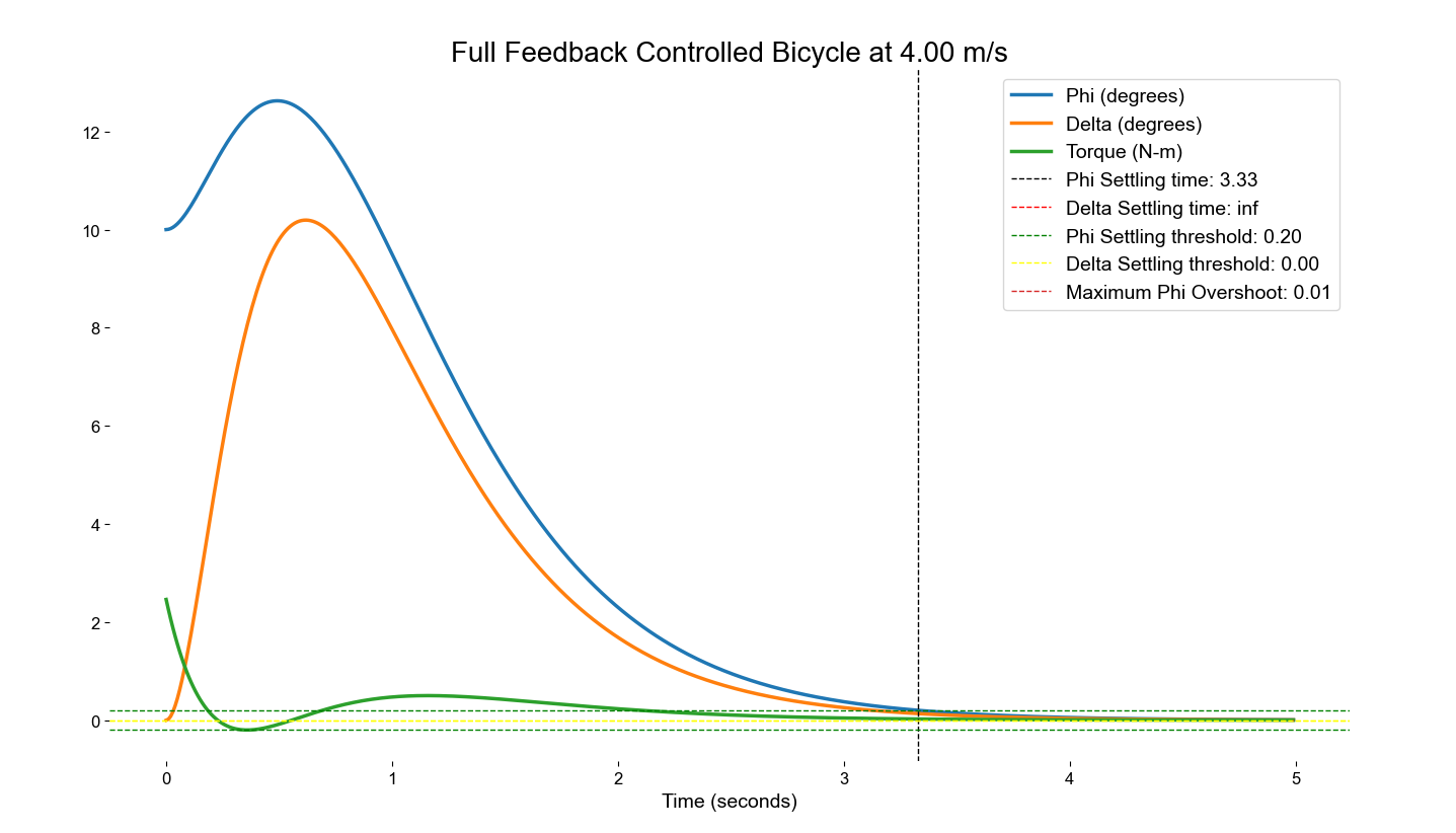
After verifying the efficacy of the controller in simulation, it was time to move to the robotic prototype.
Firmware Implementation
I implemented both the control and state estimation elements of the system in C++, running on an Atmel SAM 32-bit microcontroller. The firmware handled communications with other devices (via cables and radio), managing of the state machine for the autonomous bike, calculating the current state and control outputs, and logging data for each test we ran. The full repository can be found here.