Boppo: Design, Build, and Failure Report
A little over a year ago, I had an idea: Why aren't there more stabbing-based combat robots? The meta is currently dominated by vertical and horizontal spinners, with some hammers, lifters, and flippers, but almost no stabbers. After asking some folks with more practical experience and historical knowledge than myself, it turns out there in fact had been a few rare stabbers. The vast majority were/are pneumatic designs, holding a reservoir on board that is then dumped into a cylinder with a weapon attached. However, especially at lower weight classes, designs like these face problems due to the additional weight and bulk of the reservoir, as well as the time to reset the weapon, making them not very competitive against spinners. There have also been a few designs based on used a large spring and an electric motor to wind up the spring, with similar issues. But as far as I could tell, no one had tried using a large solenoid.
A solenoid offers several advantages that the aforementioned systems lack. First, it can take advantage of the incredible energy density of modern LiPo batteries, one of the keys to success of spinner designs. However, unlike spinners, a reciprocating solenoid doesn't have a spin up time. Every stabbing cycle should be lightning fast and identical to the previous one. Also unlike spinners, the weapon tip will continue along the line of action of the initial contact force, allowing for deep penetration of the opponent. But beyond all that, it would simply be interesting to do something very out of the ordinary for the field.
That was the thought. But just as I was getting together a serious form of the concept, COVID came, cancelling both the event I intended to bring the bot too and any access I had to the campus machine shop for several months. But, back in March, with combat robotics back on the table and renewed access to machine tools, I sat down to work in earnest on the robot that will be known for the rest of this post as Boppo.
Designing a Solenoid Stabber
I didn't want to simply spit out some dimensions for a tube, wrap whatever wire I had on hand around it, and hope for the best, so I went looking for information to base my design calculations on. When designing a spinner, the equations for rotational kinetic energy are the things to reach for, but I needed something else for my quasi-coilgun. To that end "A Detailed Explanation of Solenoid Force" by Paul H. Schimpf of Eastern Washington University was very helpful in walking through the practical design considerations for a real solenoid system.
While Dr. Schimpf was interested in the force profile of the solenoid, my main interest was the difference in potential energy between the fully retracted and fully extended state. By looking at this difference, I could find the kinetic energy transferred to the bolt, and as a result the weapon velocity for a given mass. Since I wanted the solenoid to reciprocate back (to fire repeatedly), I also needed to add a term for the energy absorbed by the recoil spring. After throwing the resulting equations in spreadsheet and fiddling with parameters (bolt mass and dimensions, desired velocity and energy, etc) for a few hours, I arrived at what looked like reasonable numbers for the coil.
Except of course, there are constraints on what kind of current can run through a coil. While the output energy of the solenoid was quadratic in the voltage I applied across it, so was the power resistively dissipated by it. So, adding in terms for the steady state current, and iteratively evaluating the total length of wire needed for the coil (as the effective diameter changes with each layer), after quite a few more hours of optimization I finally came to my final parameters: 3.7V applied across 23.5ft of 12AWG wire wound around a 1.25in outer diameter barrel, containing a 200 gram low carbon steel bolt with a threaded on hardened steel impactor, with a weapon energy of 310J for every cycle.
It was time to translate this to CAD.
Moving to an actual physical design, I had to add in considerations that didn't exist in the equations for optimization. How would the solenoid coil be kept in place? How would the barrel be mounted? How would the recoil spring and weapon elements stack up?
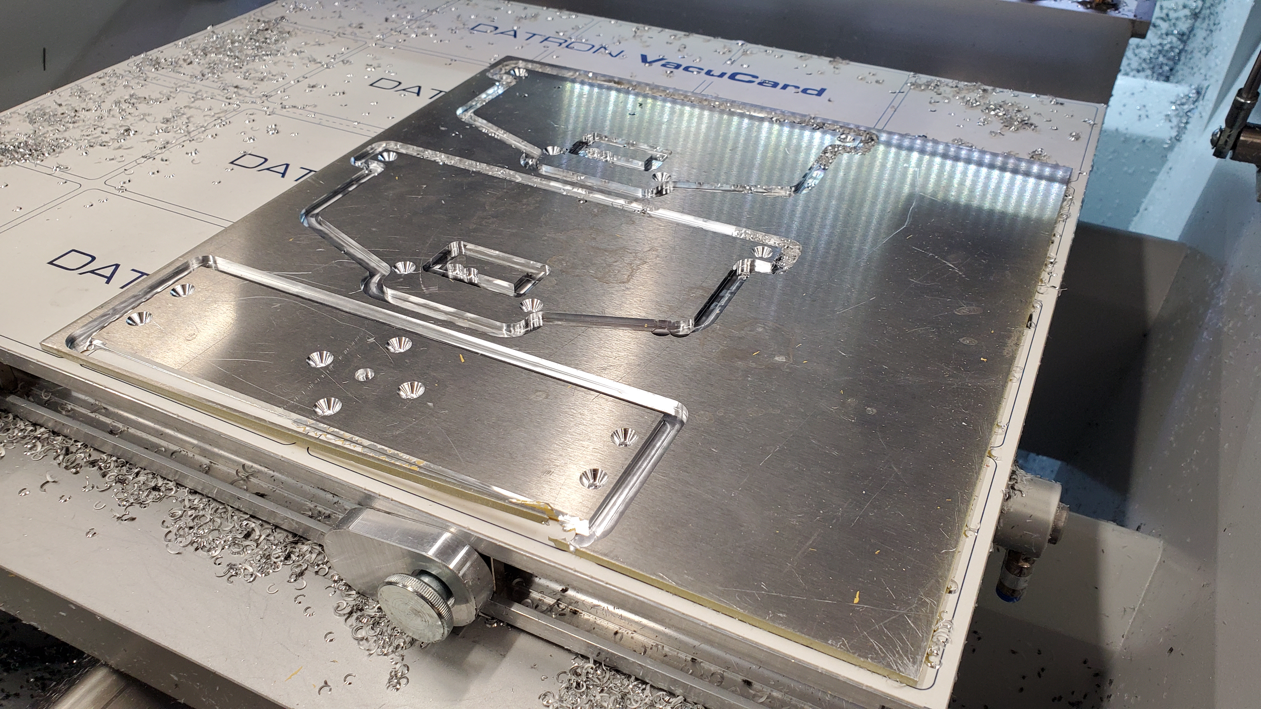
And of course, what would the robot that actually carried the weapon look like? Since I hadn't left myself much time, and I knew I would need to pour a lot of time into manually turning the parts for the weapon system, I made the chassis with components that I could either 3D-print or very easily CNC mill using vacuum workholding. The result was the following boxy boi:
The main structure was PETG, with the front and top plates made of 1/8in 6061 aluminum. They were joined together to each other and the acrylic bottom plate with small machined 6061 "posts", with all fasteners being 3/8in #8-32 flathead screws. With the design done, prints made, and materials acquired, it was time to make the thing.
Machining and Manufacture
By the time most of the designing was done, there wasn't much time left before the competition. Thankfully, that time in particular was Spring Break, so I was able to dedicate my full energies to cranking out this bot. For five days, my schedule was roughly: Wake up, set a print going, head in to the machine shop, work until the late afternoon, head home for dinner, head back into the machine shop until late at night, head back home and sleep.
The printed parts I ran on my personal Prusa MINI out of two colors of PETG. While PETG has far from the impact characteristics I wanted (TPU would have been much better), it was the better choice of what I had (the other being PLA).
The vast majority of my time was dedicated to turning the components for the weapon (which I did on the manual lathe of the Instructional Fabrication Lab). First, I turned the bolt from low carbon steel, bringing in the length, outer diameter, and drilling and tapping a hole for mounting the impactor.
Next came the impactor. Seeing as the segment of waste linear rod I was using for this purpose was already hardened, I ground the tip in with a Dremel. In order to form the threads which would mount it to the bolt, I did some blowtorch annealing of the rear section, and then with copious amount of tapping fluid, swearing, and elbow grease finally got the die to bite.
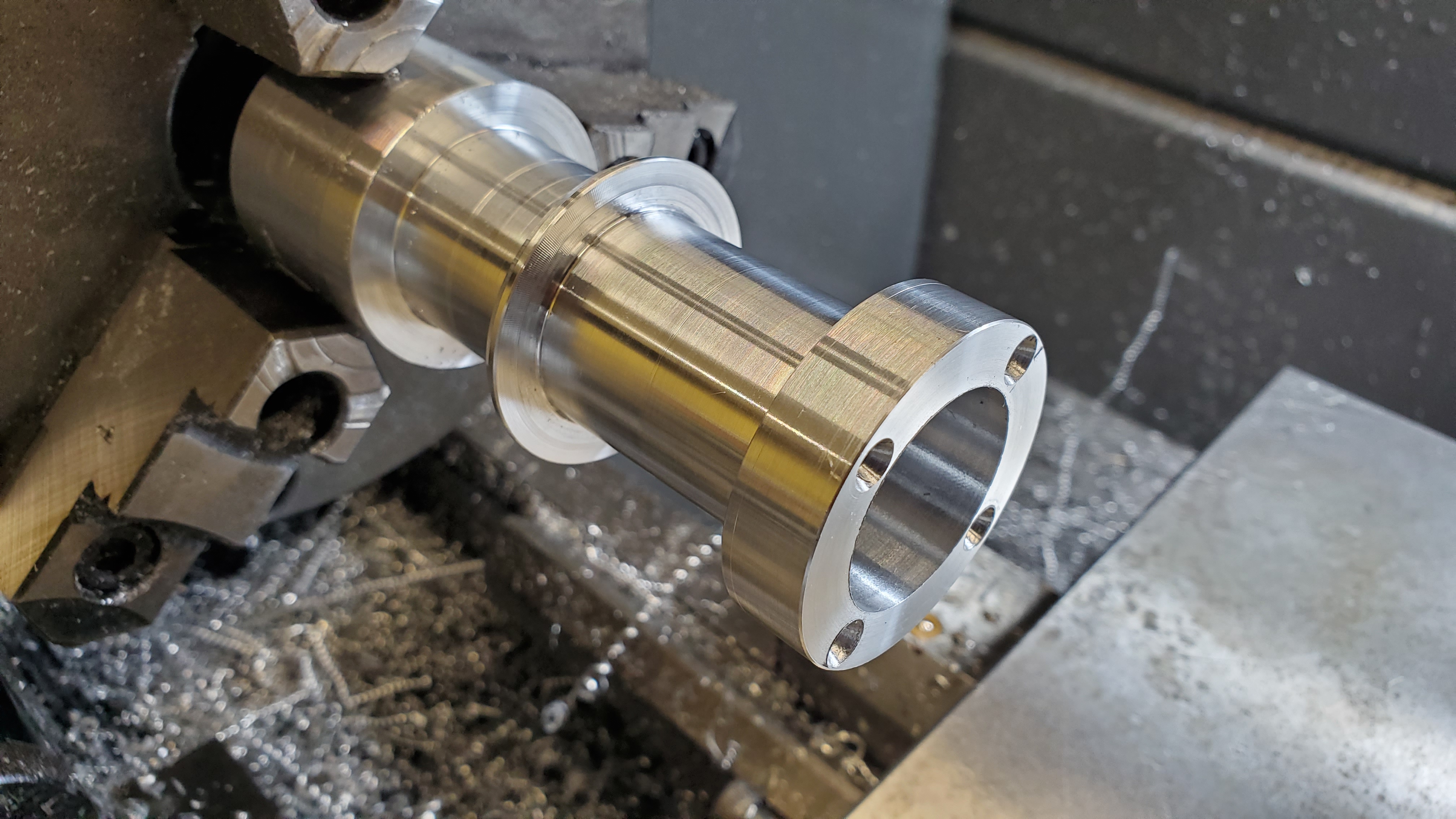
And then, of course, there was the barrel. The material efficient way to make this would have been to buy a thin tube with the right inner diameter and a number of disc to use as flanges, and weld those on, then finish machine everything. However, given how thin I was making the barrel tube and my relative inexperience TIG welding, I didn't want to risk it, and so instead I bought a thick-walled tube that I would machine the entire part out of.
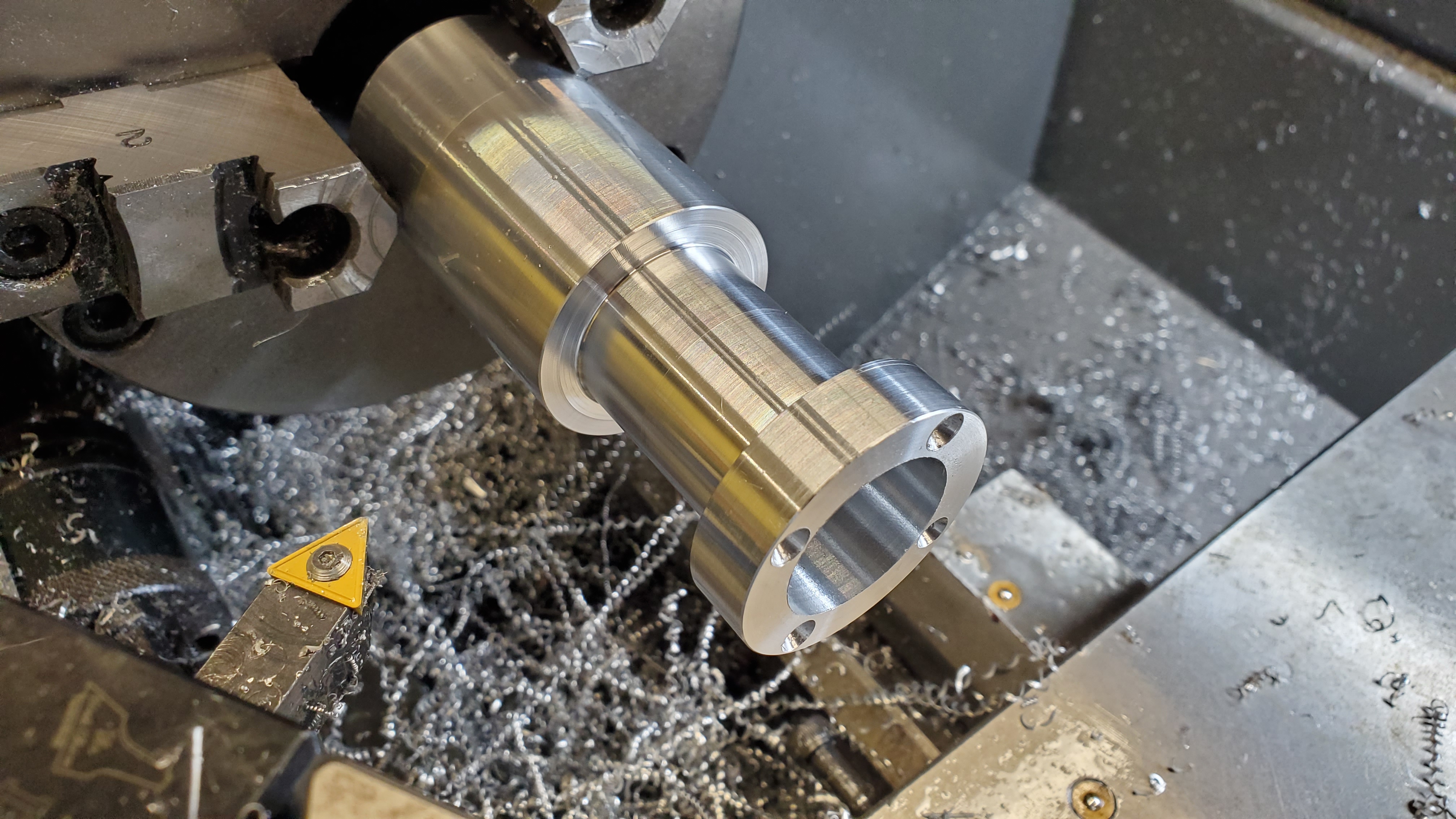
The first step was to take the OD to that of the flanges, face one end, and drill the four mounting points on one side of what would become a flange.
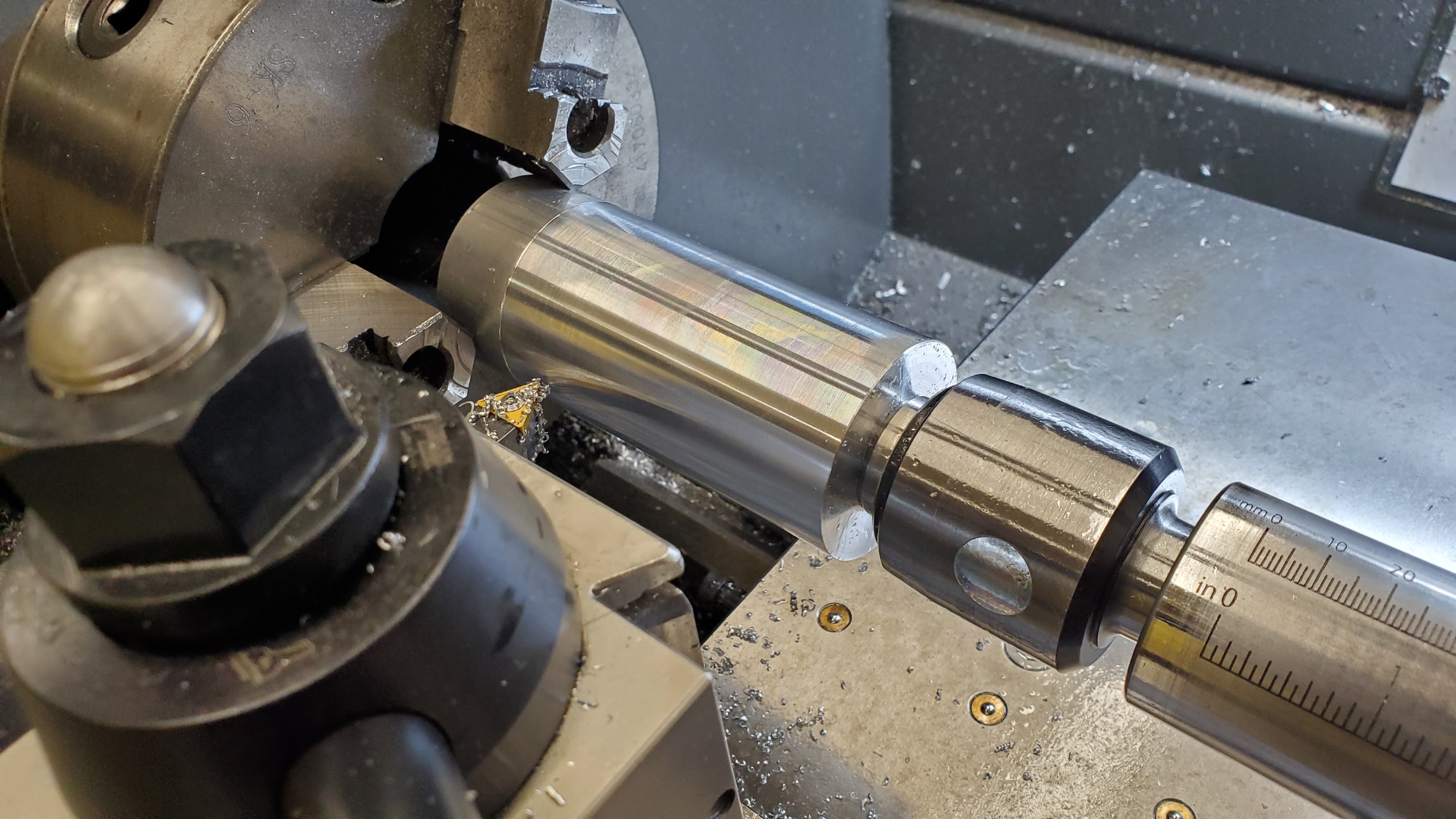
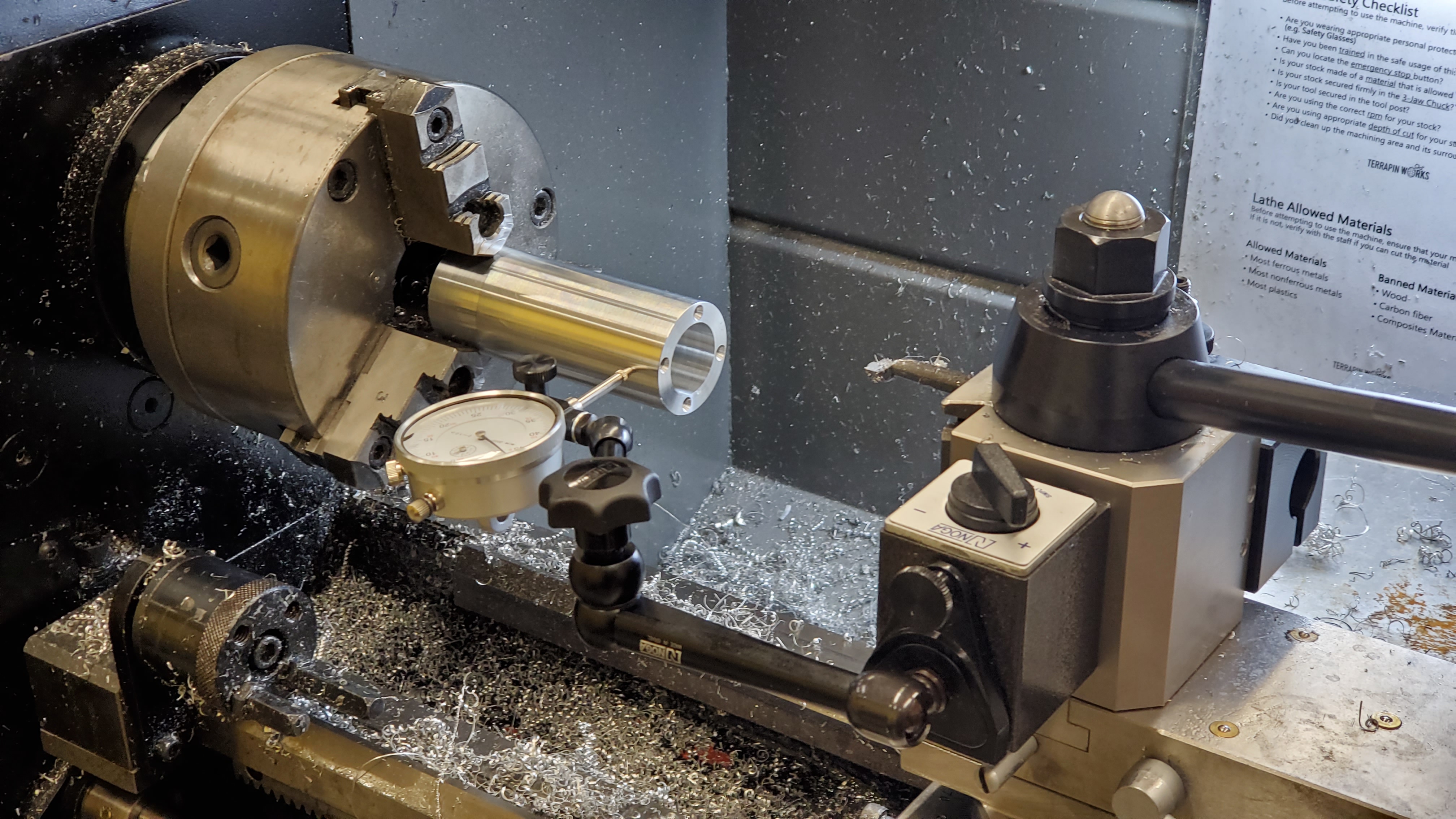
Then, I threw it back in the lathe to bore out the inner diameter. Here, I encountered an issue: the boring bar our shop has is shorter than the length of the barrel. So, I needed to do the bore in two operation, flipping the barrel around to do the second half. To ensure concentricity, I indicated both sides in, but given that the shop also lacks a four jaw chuck this was large a matter of trial and error (and prayer).
With the bore done, it was a matter of removing all the material that would form the troughs, one of which would hold the coil, while the other was simply for weight reduction.
And finally, the coil itself. The stiffness of the single-core 12 gauge wire was a blessing and a curse, since while it meant in general the stuff was unwieldy, it would also hold its shape very nicely after being bent. And so, with great patience and judicious use of the jog button on the lathe, the three layers of the coil took shape.
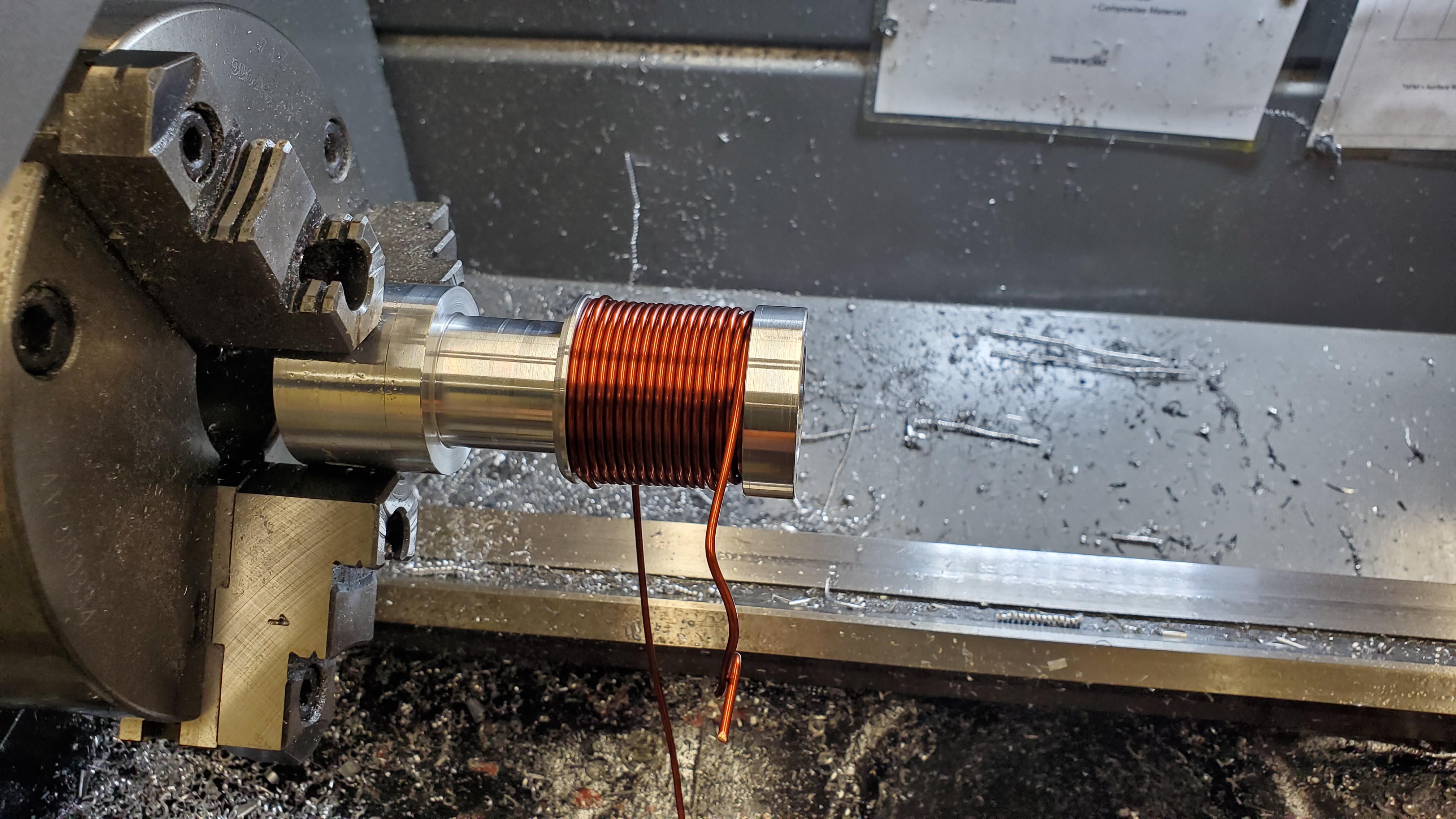
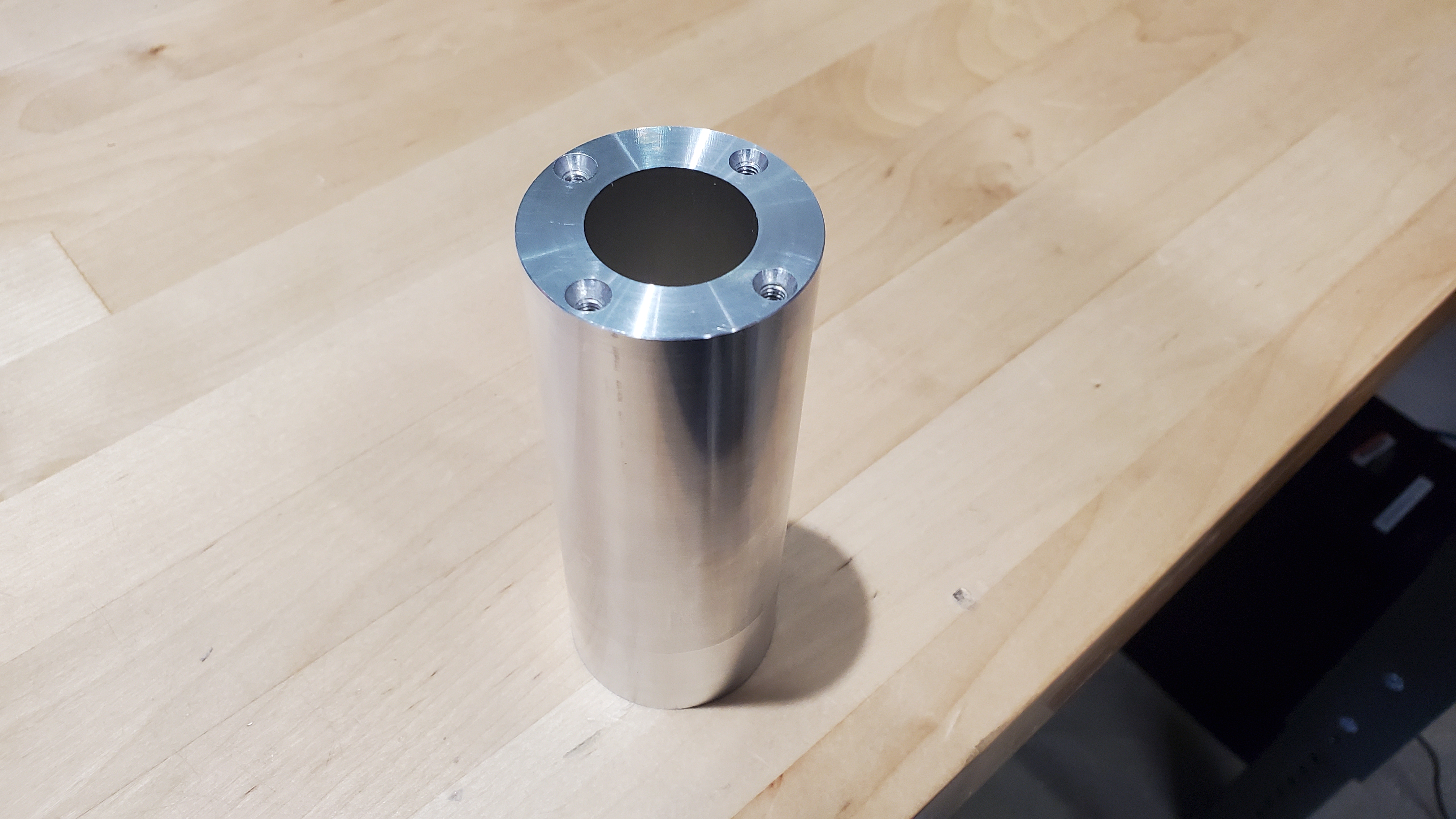
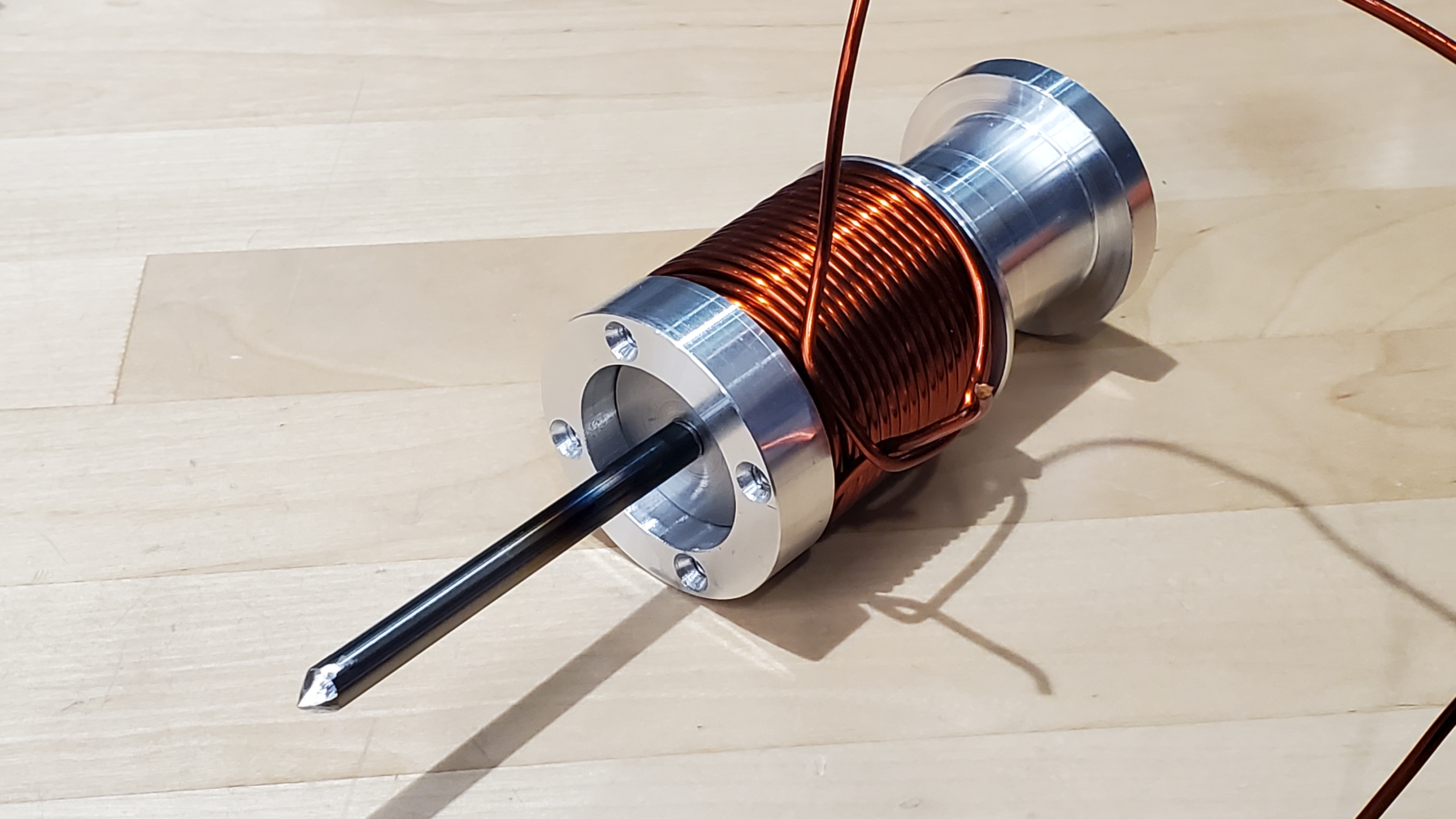
After parting off, and having completed the principal components of the weapon, it was time for a fit test.
The plates (front, top, and bottom) I cut fairly quickly on our Datron NEO.
The two components I don't have images of machining are the supporting/joining "posts". For some reason (probably the annoyingness in workholding for small parts) these took me longer than they reasonably should have, and resulted in me scrapping one due to incorrect dimensions and breaking a tap in another. Let's just say that after this I'm never using the drill press when I could use our manual mill instead.
With all of the parts done, it was time to lay things up.
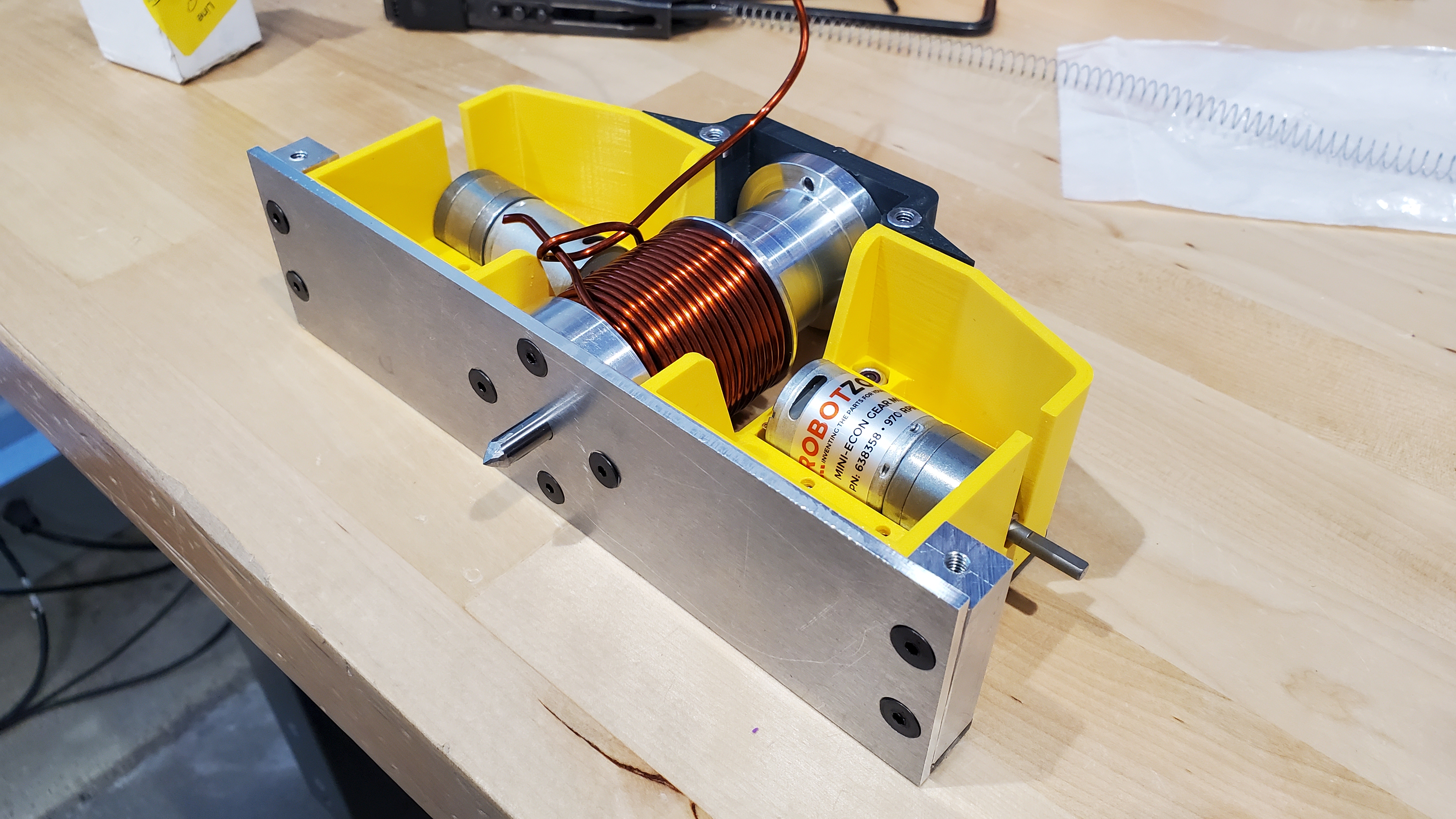
Everything looked good. Except for the total absence of electronics, and wheels. So with barely any time to spare before leaving for the competition, I soldered those together (and the wheels arrived literally as I was doing that).
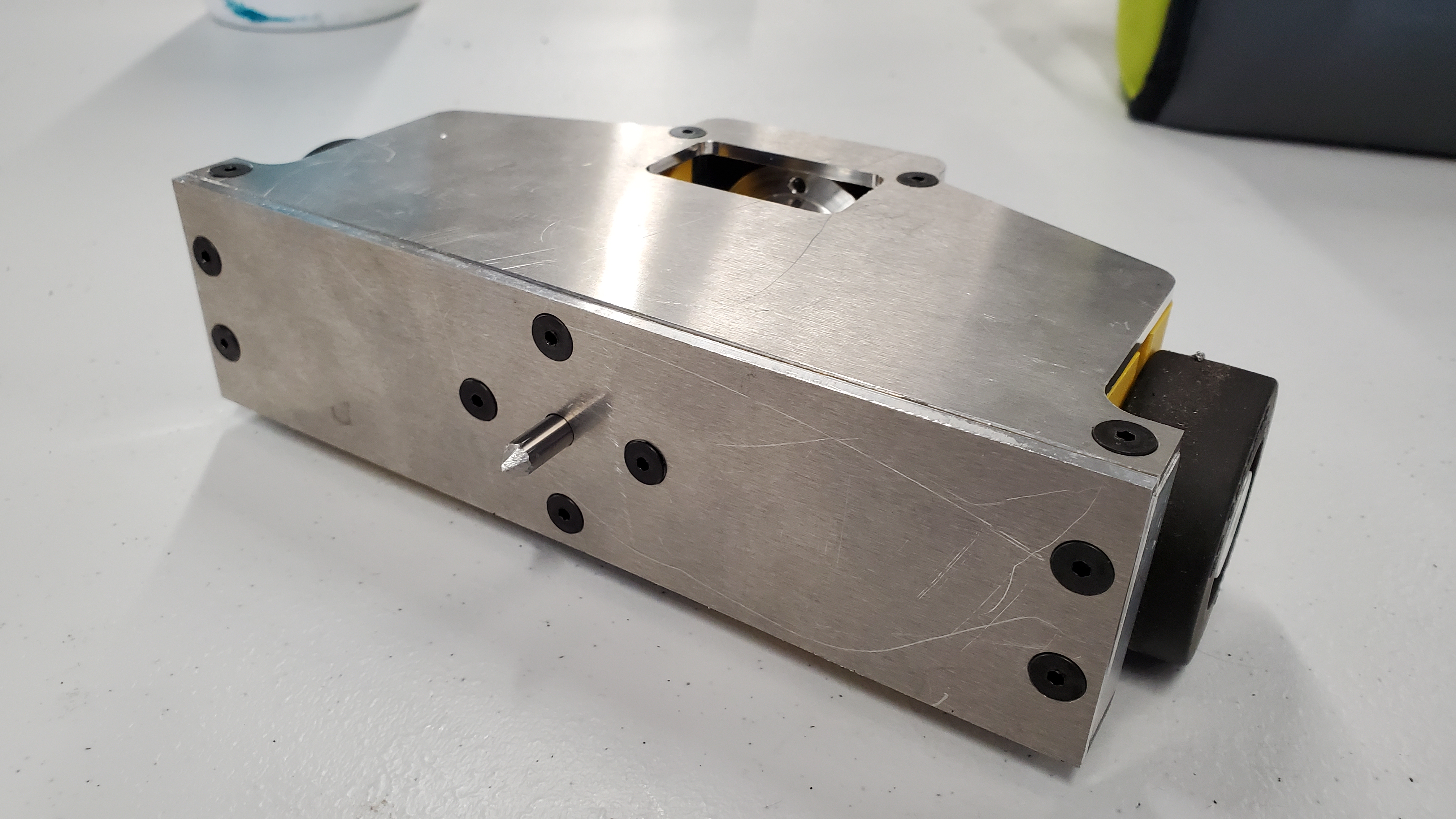
Much better. And so it was time to drive up to Norwalk.
Why It Didn't Work
The robot didn't work. Now, I don't mean it didn't fight very well. I didn't end up fighting with it since the weapon simply did not function well. So let's dig into what happened and why.
First, I was relatively inexperienced with integrating new hardware into RC systems (I hadn't done much of the wiring on our team's previous bots, doing more of the mechanical design and machining). So, I had foolishly assumed that the RC 'PWM' channels could give out 0 to full duty cycle PWM, and so could drive the relay I had chosen as the fire control system for the coil. This, to my chagrin, is not the case, as RC PWM outputs lie in a very specific range of pulse and period that can never directly drive anything really. However, I did have a spare TinyESC which I hooked up, and as that is a brushed, encoderless ESC I was able to trick it into driving the relay.
Great. Except the weapon wouldn't fire. Why? The relay was cycling as intended. Well, it turns out the 1s batteries I had bought, despite their stated C rating and the fact that I had three wired in parallel, had a short circuit current of only 8 amps, too little to even overcome the recoil spring.
So, in desperation, I hooked up my 4S drive battery to the weapon system. And the weapon fired! Once. And then it didn't do anything else. Since the relay I had grabbed in my rush was only rated for 10 amps. After confirming that it was in fact, completely fried, I had to give up.
Honestly, this may have been a blessing in disguise, as the robot's chassis would have likely shattered upon first contact with the enemy, and then who knows how badly the painstakingly made weapon assembly would have been beat up for little to no gain.
So where do we go from here?
What's Coming
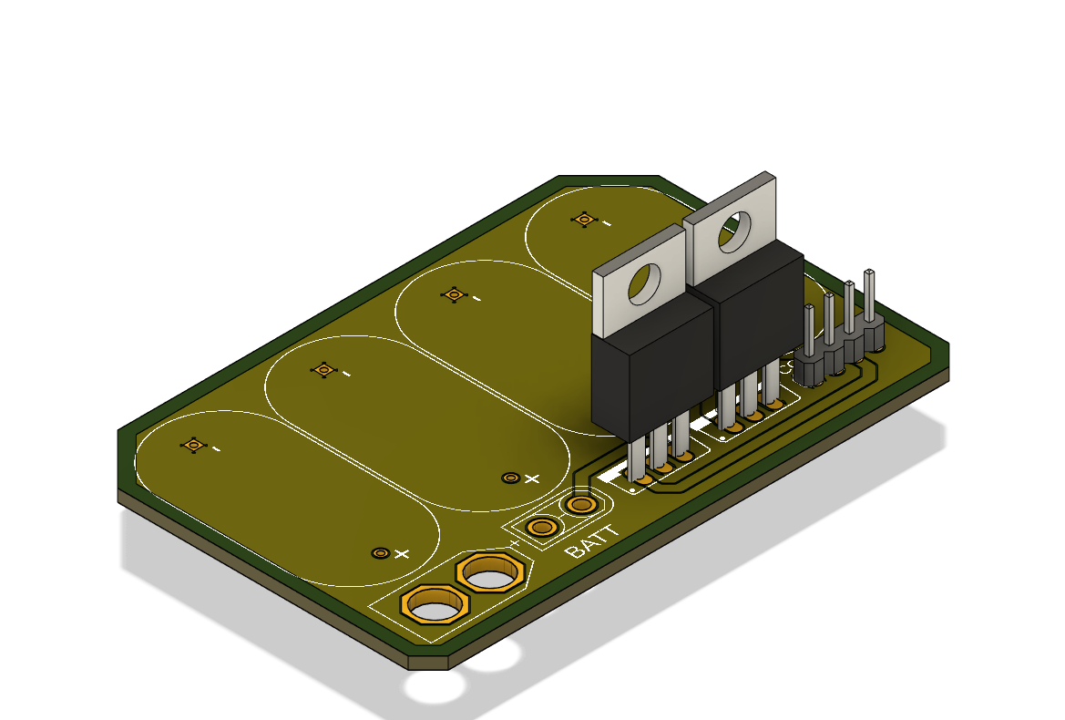
I've been working on rework of the fire control group for the robot which should solve my issues in both sourcing and controlling the high current needed. Let's just say it involves a custom PCB, beefy mosfets, and the word "supercapacitors". More info to come.
Due to the space needed to accommodate the new electronics and inherent weaknesses in my initial rushed design, I will also be reworking the chassis. So, with these improvements, we should have a chance to see if my wacky stabbing concept is actually even mildly viable at July's Norwalk event.